Downloading KanexPro software and firmware safely
How KanexPro checks firmware and software downloads, how to verify a file's SHA-256 fingerprint, what the Windows SmartScreen warning means, and…


This guide covers a typical full-room AV control deployment using KanexPro Controls products — combining a central processor, wall keypads or a touch panel, and extenders to control displays, sources, audio, and lighting from a single system, all programmed using EasyAccomplish.
| Room Size | Processor | UI Device | Expander (if needed) |
|---|---|---|---|
| Small huddle room | CR-HOST6S | CR-KEY8U or WP-IPKEYPAD8 | — |
| Medium conference room | CR-HOST6S | CR-TOUCH4A | CR-EXPAND1 |
| Large boardroom / auditorium | CR-HOST8R | CR-TOUCH6R + CR-KEY10R | CR-EXPAND4 |
How KanexPro checks firmware and software downloads, how to verify a file's SHA-256 fingerprint, what the Windows SmartScreen warning means, and…
Boardrooms, conference rooms, campuses, lobbies — real-world deployment scenarios Corporate AV is among the most practical deployment target for…
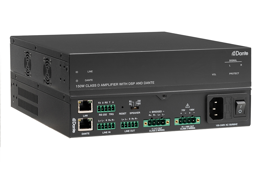
Setup Guide Configuring Your Network Switch for Dante Required switch settings for all KanexPro AUD-DTE- Dante products Dante requires a managed…
KanexPro sells direct to dealers, resellers, installers and integrators, and through distribution. Whichever way you buy, the same engineers answer the phone.
The trade store: your own account, live stock, reordering, and a first look at new products.
Go to the trade store →Distribution and authorised resellers across the US and beyond.
See where to buy →Design help on extenders, matrix and AV over IP before you spec it.
Ask an engineer →